Dominant Massey Ferguson balers
Posted by Chris Graham on 26th June 2020
Dan Harris explains how and why, from the early 1950s onwards, dominant Massey Ferguson balers were so influential in UK farming.
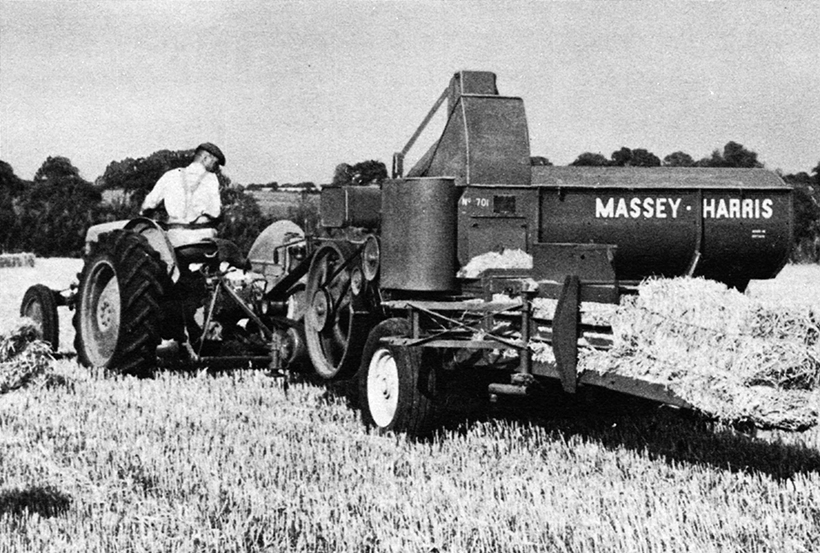
Dominant Massey Ferguson balers: Bales left the chamber on their narrow side from the MH 701 model. Note the needles to the left-hand side.
By the time the branding of the company changed form Massey Harris to Massey Ferguson, the all-new 703 baler had been developed and launched in 1957. This model bore no resemblance to the 701 that had gone before, and was very much a clean-sheet approach. Fortunately for the development team at Massey Harris, they had some competitor models, such as the McCormick International B45 and New Holland 66, from which to take ideas.
The 703 model was the first of a new generation, which would provide the basis for baler production at Massey Ferguson for nearly two decades. It had become the new normal to turn the bale chamber, so that the bales came out on their flat, with the strings on the top and bottom faces making them particularly easy to pick up. A significant advantage of this configuration was that the feeding arrangement was considerably simpler, as the material no longer had to be elevated above the bale chamber, and could be fed in through the side instead.
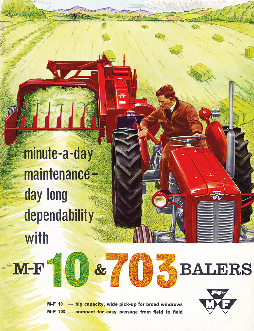
The front cover of the original sales brochure for the MF 10 and 703 balers.
Power options
When introduced, the 703 was offered with the option of either PTO drive or Petrol/TVO engine drive. On PTO models, the PTO could be specified with either a standard Society of Automotive Engineers (SAE) 1 3/8in, or a Ferguson 1 1/8in six-spline coupling. Standard specification included a long drawbar and a two-section PTO arrangement, which were found preferable on balers to permit tighter turns to be made while still baling. Power take-off guarding was of the latest, tubular type, with the shaft running internally rather than a cover-draped over the top.
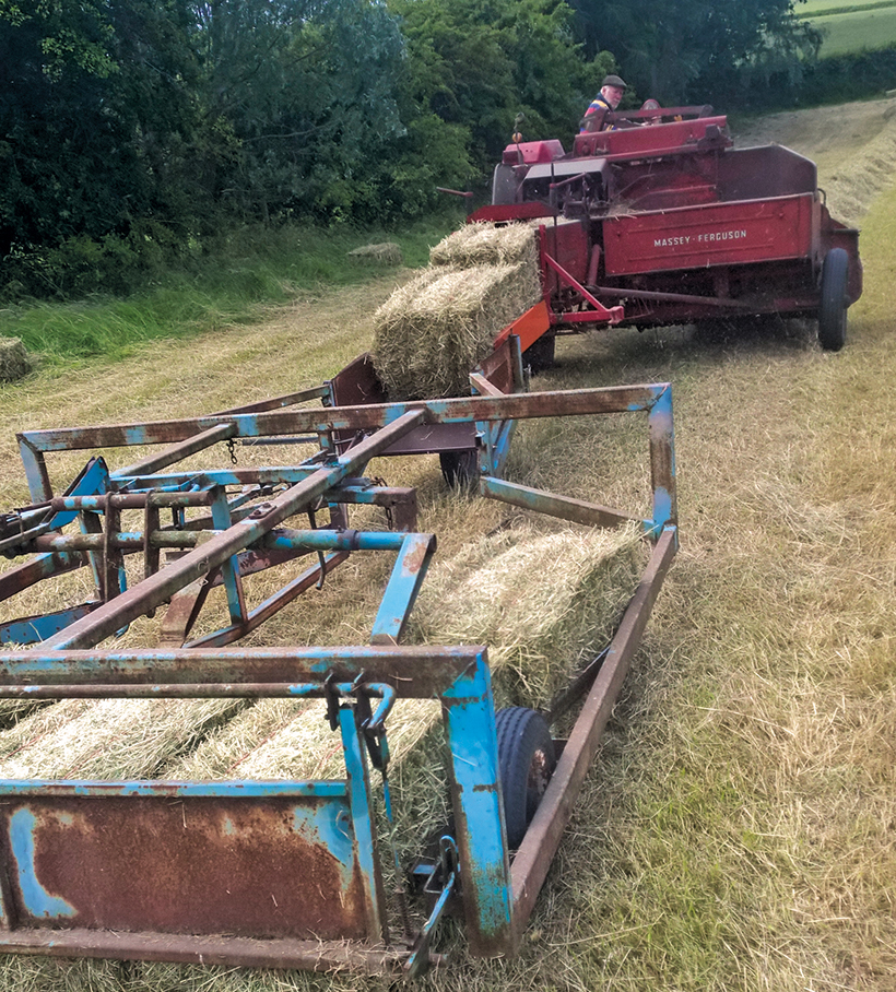
Alan Glover uses his MF 703 behind an eight-speed MF 165, and proves that the bale shape is ideal for an accumulator operation.
Engine models featured a two-cylinder JAP unit mounted above the bale chamber, producing some 13.5hp from the petrol-only version, or 12hp from the VO model, which was considered ample to drive the machine. Unlike the 701 model, engagement of the belt tensioner couldn’t be actuated from the tractor seat, and required the operator to dismount to engage and disengage the machine. Guarding around the flywheel on engine-driven machines was also reduced, since the driving belts from the engine acted directly on the periphery of the flywheel.
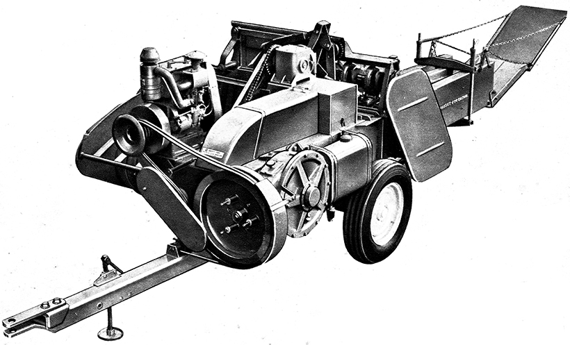
Taken from the 1958 Massey Ferguson catalogue, this 703 featured the optional, auxiliary engine drive.
The flywheel was mounted across the front of the machine so that it could be driven directly by the PTO shaft, through a combination of overload and over-run clutches; the latter an important feature to stop flywheel inertia coming back to the tractor from the baler on the run-down cycle. Flywheel orientation necessitated a new gearbox with bevel-reduction but, importantly, the ratio had changed to provide 70 strokes per minute at 540 PTO rpm. A shear bolt was also placed in the driveline, between the flywheel and gearbox, as a cover-all fail-safe.
Wide swathes tackled
The main gearbox drove a 26in stroke crank, providing the reciprocating motion to the plunger. Power was taken from the idle-end of the crank to drive a double sprocket, which provided drive to the pick-up, feeders and knotters. A pick-up with four tine bars 48 inches in width and flared side dividers enabled, swaths of up to 56 inches wide to be gathered. An over-run clutch was incorporated to protect the machine when reversing over obstacles with the pick-up down. The provision of a spring-tensioned crop guide (fitted as standard), prevented material escaping the pick-up on windy days.
While other manufacturers were generally using an auger and single feeder arm to force material into the bale chamber, Massey Ferguson came up with a memorable solution based on a pair of crank-driven fork packers. I say memorable because the action can only be described as a Springbok jumping backwards, while nodding its head! I certainly don’t recall another conventional baler with such an elaborate mechanism, that rises so high above the machine.
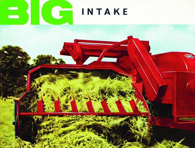
Big intake! MF was keen to promote the large, 64in gather pick-up of the model 10.
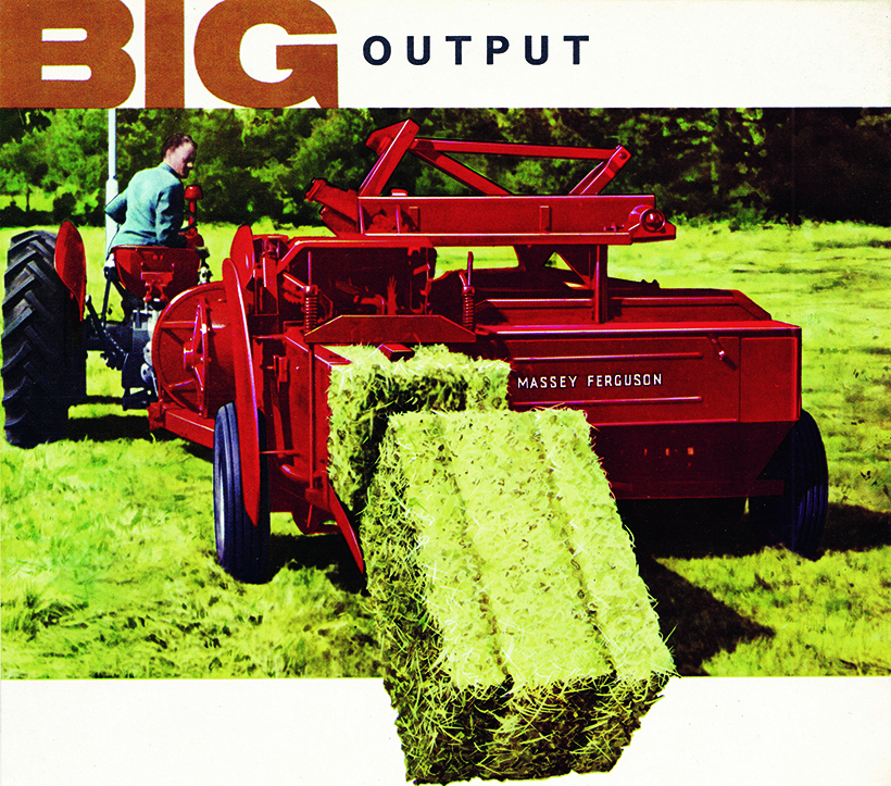
Big Output! The model 10 could hold its own against contemporaries of the day.
Important safety features
Several safety features were included in the design of the feeder, including the novel idea of using sacrificial, industrial plywood for the front feeder fingers, which would fail should the plunger strike them in the event of mis-timing. The feeder assembly driveline also included a shear bolt and a spring-release control rod for use in the event of an overload, thereby protecting not only the driveline, but also the feeder tines themselves.
As many will know, bale shape is dependent on the even fill of the bale chamber which, in turn, is dependent on the material being baled. In other words, if you don’t want ‘banana’ bales, then the feeders need to be correctly adjusted. Straw is more forgiving, but grass type and humidity makes quite a difference when baling hay. The front feeder forks were adjustable for rake, by moving the overload protection arm anchor block along its mounting. The front forks can also be placed in one of three positions, to provide a coarse adjustment if necessary.
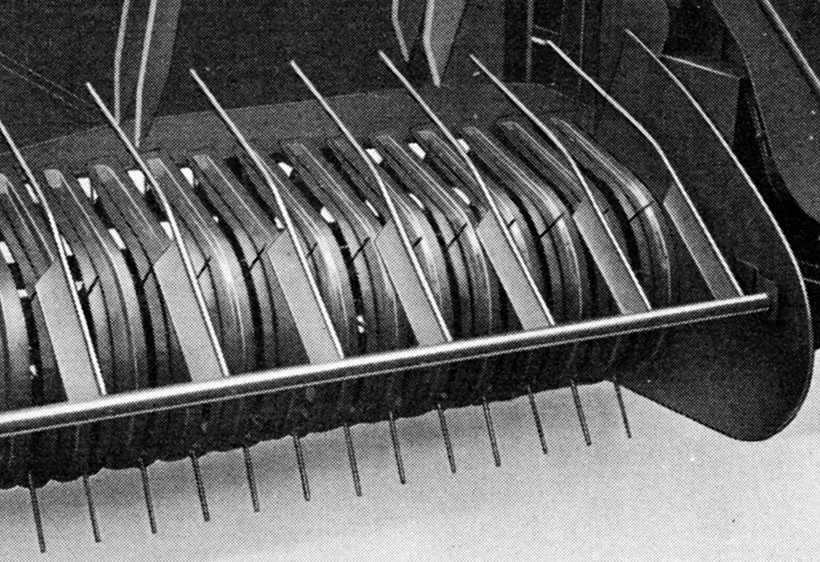
The pick-up of the model 10 in detail. Note the relatively wide spacing of the tines, and the crop guide above.
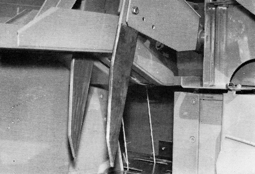
Wooden inboard feeder packers prevented damage in the event of baler mis-timing; replacements could be made from plywood.
Roller bearings for the plunger were still some way off, but at least MF had now moved away from metal wear pads sliding on metal rails, and a new composite wear pad was specified. Due to the position of the chamber shear knife, the static knife could no longer be shimmed, as in the 701, to provide the accurate knife adjustment. This resulted in more adjustment being required in the plunger guide rails, and so adjusting screws down the left side of the chamber were provided.
The knotters were very similar to that of the outgoing 701, although they now sat on the top of the bale chamber, and incorporated a knotter brake for the first time, to prevent the needles from entering the chamber between tying cycles. A number of self-lubricating bearings were used in the design of the knotters, resulting in very little daily maintenance. The knotter trip mechanism also included a new bale length adjustment feature, enabling this to be varied infinitely between 18 and 45 inches.
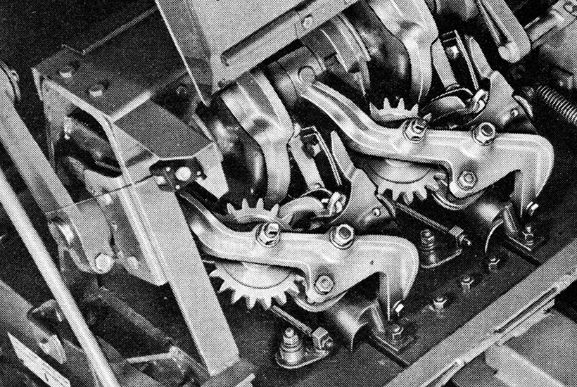
Other than the orientation, the MF knotter was little changed between the outgoing 701, and the new 703/10.
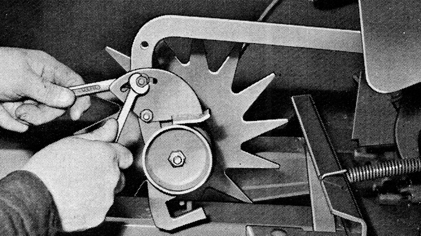
The trip mechanism made provision for infinite bale length adjustment in the range 18-45in.
Needle position
With the knotters on top of the bale chamber, the needles were required to be positioned under the bale chamber, and were protected by underslung guards to prevent damage when reversing over bales, as many people – myself included – have done. Importantly, the needles were further protected by a plunger stop, should a timing fault leave the needles in the path of the oncoming plunger. The shear bolt would simply fail and be considerably cheaper to replace than a set of needles.
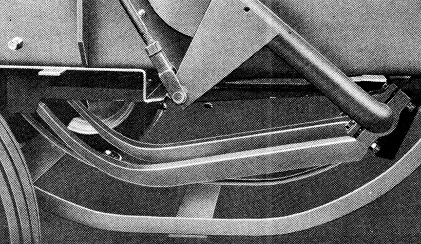
With the needles slung under the bale chamber, protection was provided to prevent accidental damage.
Bale tension was applied with two screw handles on the top of the rear portion of the bale chamber. But, if additional bale density was required – as with very dry crops – then wedges could be fitted to the internal side faces of the bale chamber. Bales exited on to either a single or split-section tailgate; the split section permitted one half to be removed, creating a tailgate necessary to deflect bales out of the path of the tractor on the proceeding round, when baling narrow mower swaths.
The MF 10 machine, launched at the start of the 1960s, is an almost identical baler, but with an eight-inch wider pick-up to accommodate the wider windrows, especially useful when following the larger combine harvesters of the day. It was also becoming common practice to windrow two separate mower swaths into one, to reduce trips around the field, with the added advantage that bales were left in denser rows for subsequent collection.
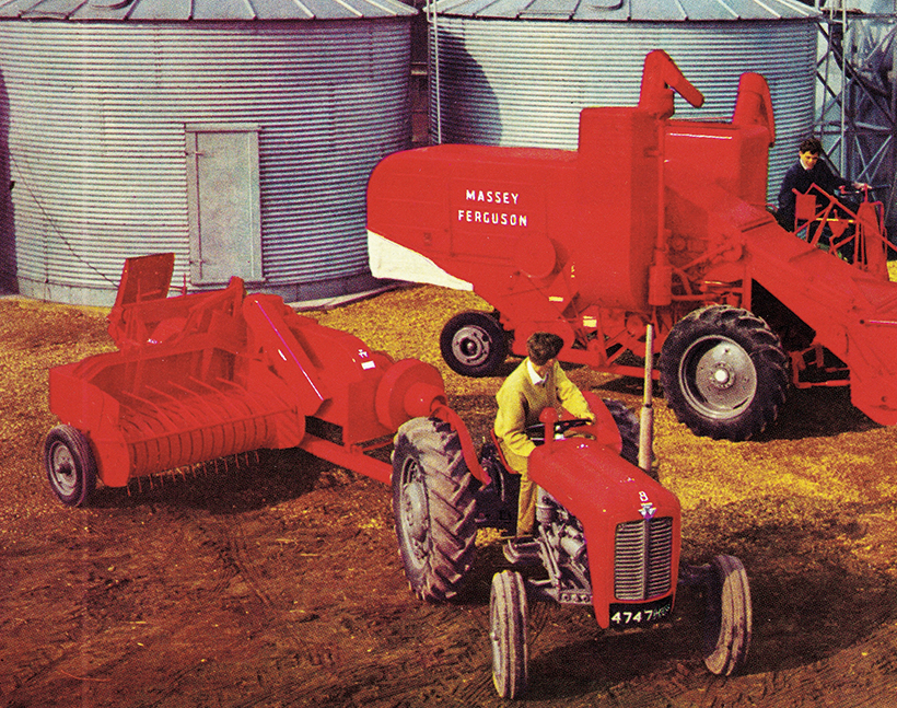
The model 10 baler complemented the tractors and combines produced by the company in the early 1960s.
Production of MF conventional balers ceased at the Kilmarnock plant during the early 1960s, to make way for the building of MF 400/500 combines, which came online for the 1962 season. Baler production was transferred to Massey Ferguson’s Marquette baler and combine plant in France, leaving the Kilmarnock factory to concentrate on combine production.
Development can never stand still, and the MF 703/10 balers provided a useful platform on which to build the style and function of the MF conventional balers for years to come. There was to be stiff competition from the likes of International and New Holland, but companies such as Jones and Bamford were clearly taking a significant market share in the early 1960s, with all manufacturers looking to produce balers of higher output.
The MF 15-20
The MF 15 and MF 20 balers, launched in approximately 1963, were the response to this ever-increasing competition, and built on the success of the MF 703 and MF 10. Keen to keep the family look between the two new models, sheet metal styling was very similar, although the MF 20 had a more enclosed surround to the feeder cranks. Other than the differing widths of the pick-up, and the shorter drawbar and single-section PTO shaft of the MF 15, they were essentially the same baler.
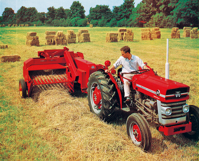
Development never stands still, and the model 703 was replaced by the model 15, shown here behind a MF 135.
Both machines did, however, benefit from a range of new features, none more important to productivity than the hypoid bevelled gearbox, with advertised plunger speeds of 70-80 strokes per minute at 540-610 PTO rpm. MF was now actively encouraging operators to run the baler at up to 610rpm PTO speed to get the best from it. The plunger stroke had also been increased by two inches, resulting in an increased area for the opening between feeders and bale chamber.
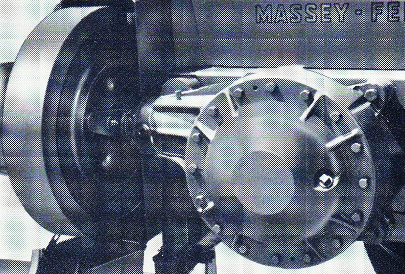
An entirely new hypoid bevel main gearbox was introduced with the model 15 and 20.
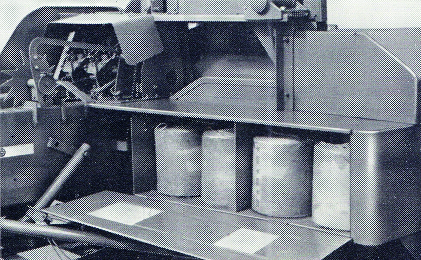
Like their predecessors, the model 15 and 20 balers carried four balls of string.
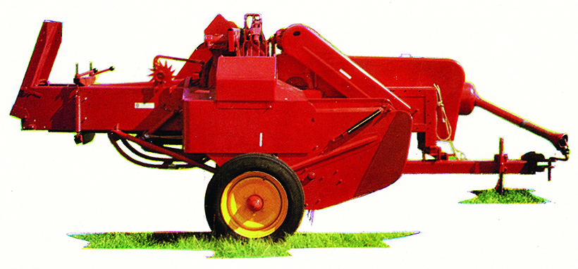
The right-hand profile of the model 15 is almost identical to the model 20, but note the reduced tinwork around the feeders.
Claimed outputs were 10 and 11 tons an hour for the MF 15 and MF 20, respectively. The sales literature also claimed that a daily output of 3,000 bales was possible with either machine. But, even with a new machine, I’d think that those figures would be more than a typical day. With the increased output, the pick-up also had to be speeded up to suit but, other than that, the balers remained largely the same mechanically as the models they replaced.
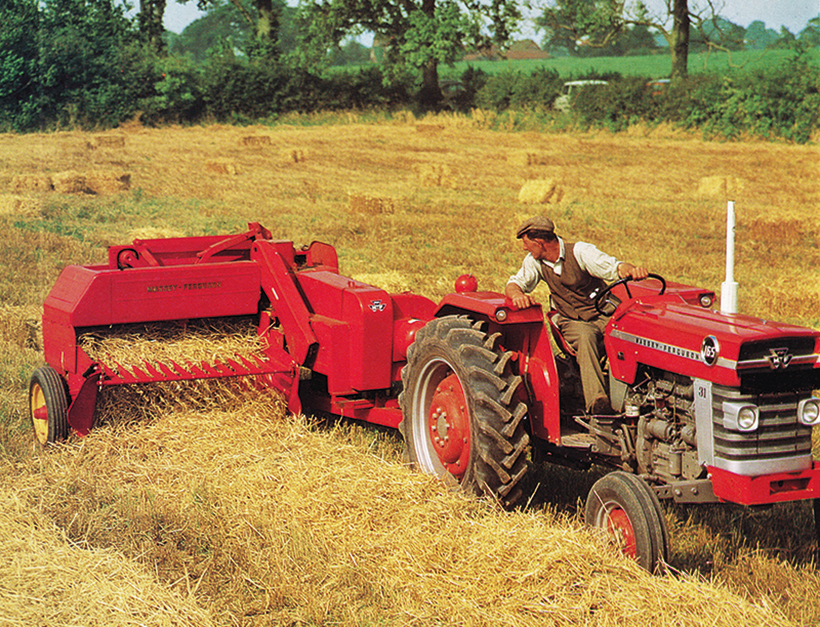
Likewise, the model 10 was replaced by the model 20 and, although very similar, the plunger stroke was two inches longer on this model.
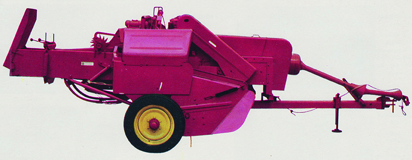
The right-hand profile of the model 20, with larger, more purposeful enclosure of the feeder arrangement.
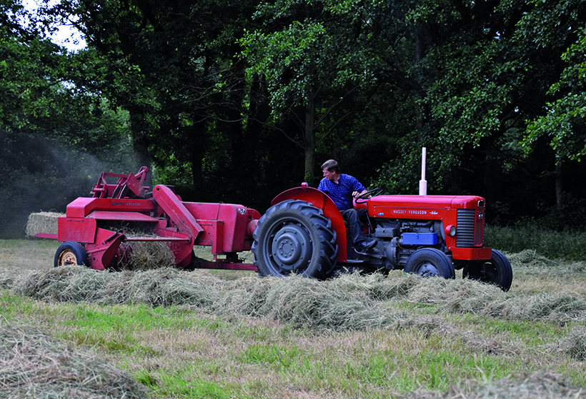
Melvin Stamp purchased this original, one-owner MF 15 recently, to use behind the MF 65 on his smallholding.
Essential greasing needs
Interestingly, the daily greasing requirement had increased to four nipples, which implied that reliability could only be achieved with the correctly administered maintenance, and that there was no substitute for regular re-lubrication. For the UK market, the plunger still ran on composite pads, but continental MF 20 models were supplied with a plunger running on six rollers. It seems odd that the UK customers had a different specification machine, but I’m sure there was a reason behind it.
Within a few years, the MF 15 and MF 20 ranges were tweaked again, receiving a different ratio gearset in the main gearbox, pushing plunger speeds to between 80-90 strokes per minute. The MF 20 also benefitted from an additional set of packer fingers sandwiched between the existing pair, and these two mods alone gave a claimed, additional output of four tons per hour. The MF 20 was now capable of 15 tons per hour and the model had truly come of age, proving to be a very popular machine.
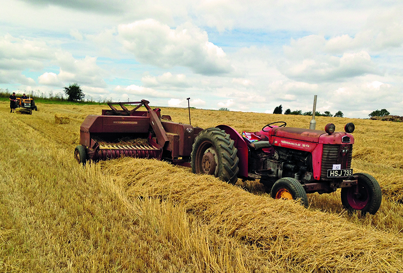
Edward Garner still uses this MF 20, supplied new from Browns of Leighton Buzzard, operated by this MF 65 or an MF 135.
The MF 120-128
When it came to revamping the balers again MF, for the first time in nearly 20 years, decided that it was once again time for a completely new approach. It was now the mid-1970s and other manufacturers, such as John Deere, had entered the European market, all with high plunger speeds running on roller bearings.
The new baler would only retain the dependable, hypoid bevel main gearbox from the preceding models. The all-new baler was designated the MF 124, and was introduced for the 1976 season, being initially sold alongside the outgoing MF 15 and MF 20. Later, a three-machine range would be offered, including the reduced-specification version the MF 120 and a wider pick-up MF 128 model for following ever-larger combines.
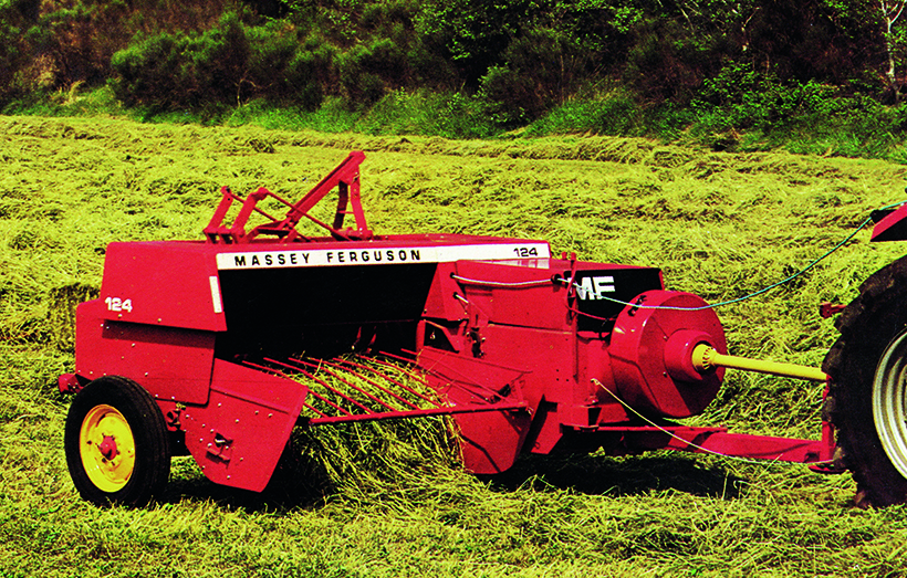
The MF 124 was introduced in 1976 and was, once again, a clean-sheet approach to baler development.
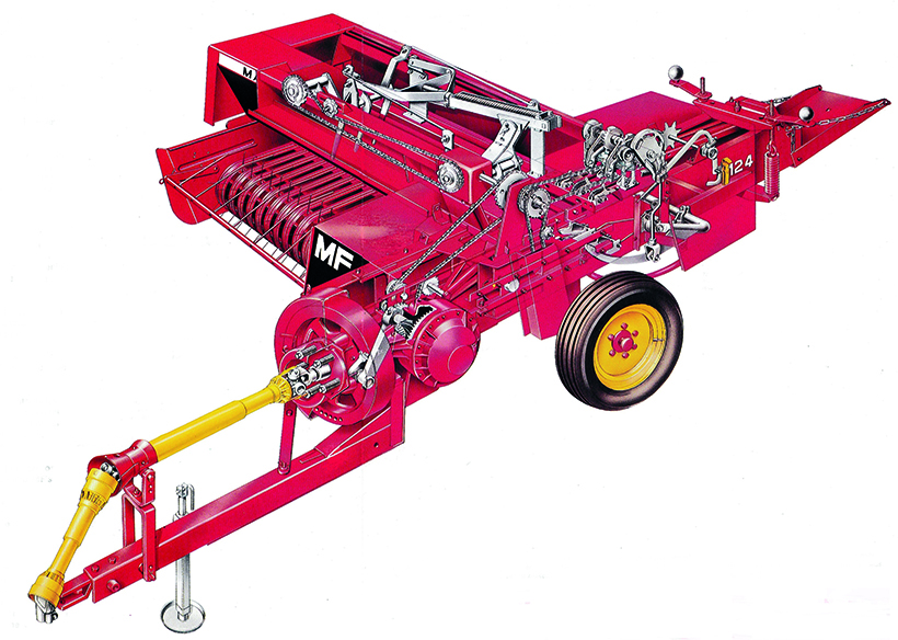
This cutaway illustration of the model 124 displays the power transmission arrangement to the feeders and knotters.
A double-section PTO shaft was specified, driving the flywheel through a slip and overrun clutch assembly, as was standard practice. Conserved flywheel energy was said to be increased by 20% over the previous designs, achieved by moving more of the metal from the now spoked centre, to the periphery band instead. Massey Ferguson elected to keep the same main gearbox ratio, delivering 80-90 strokes per minute at 540-610 PTO rpm.
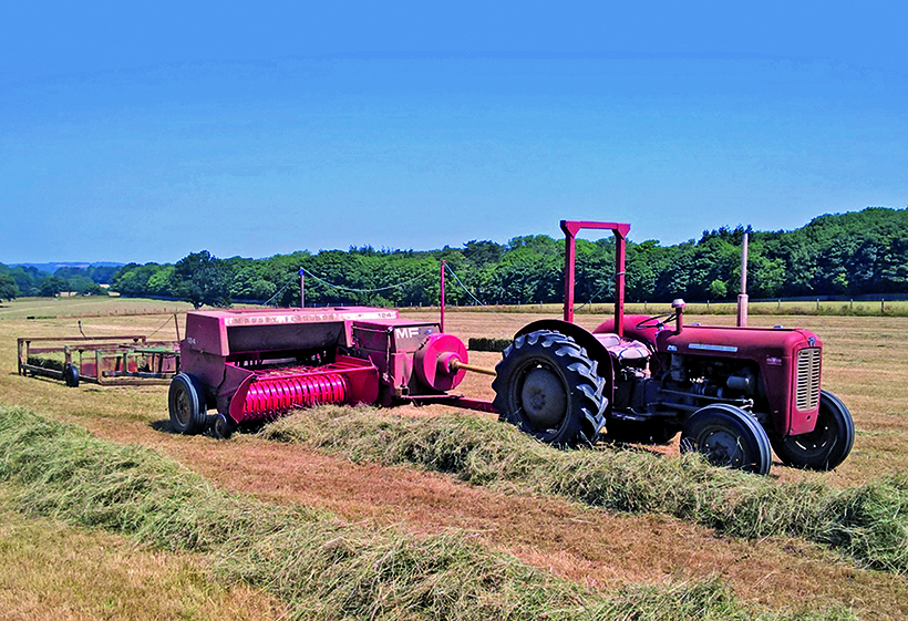
Brian Davies, who works for St Fagans National Museum of History, operates this immaculate MF 124 on the Museum’s farm.
The plunger stroke, however, was increased to 30in on the MF 124/128, thereby increasing the feed opening to the chamber still further. Crucially, the composite wear pads, which featured on the previous generation of balers, had been replaced by three rollers. Two rollers in the base of the plunger ran on a trapezoidal rail, for accuracy in maintaining the clearance of the shear knife interface. The plunger chamber also incorporated raised channels to produce a bale with grooves in which the twine sat.
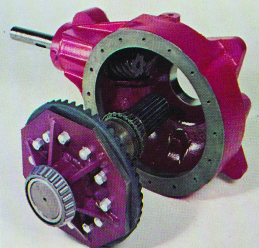
Only the hypoid bevel gearbox was retained from the outgoing model 15 and 20 balers.
The drive chain for auxiliary functions was now retained within the bale crank guarding, by mounting the drive sprocket between the main gearbox and the crank. This drive provided the motive power to a new feeder arrangement featuring twin feeder cranks, each with a set of three feeder tines. The MF 128 would feature an additional set of feeder forks to ensure the wider feeding area was swept effectively. The left-hand set of feeder forks, closest to the bale chamber, incorporated the ability to set the tines in one of three positions, to adjust chamber filling.
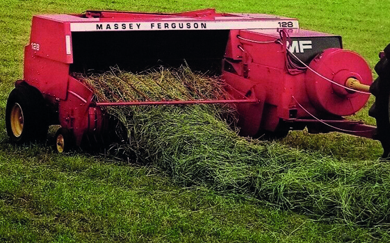
The MF 128 featured a 12in wider pick-up than the MF 124, and also a triple row of packers to sweep it.
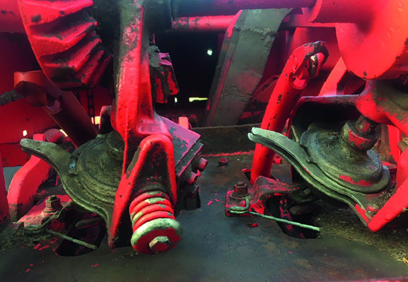
The Suretie knotters that made the MF 124 baler famous, and won a RASE silver medal in 1976.
Notable upgrades
Upgrades to the floating pick-up included five tine bars on the MF 124 and MF 128, while the reduced specification MF 120 continued to use four tine bars. On all models, the tines were spaced closer together to give a cleaner pick-up, especially on short and brittle straw. A remote-control pick-up raise and lower feature was available on the MF 124 and MF 128, featuring a rope wrapped around the feeder gearbox input shaft which, when tightened by the operator, allowed the pick-up height to be set in a pre-set position. A rope was also provided to enable the drawbar to be moved between ‘work’ and ‘transport’, from the tractor seat.
The greatest development in the new range of balers was the ‘Sure-Tie’ knotter, which was a far simpler mechanism than anything produced by either Massey Ferguson or any other manufacturer, before or since. Essentially, the design featured the bill hook running down the centre of the twine retainer, negating the requirement for a stripper arm. Recognised as a significant development at the time, it was awarded the Royal Agricultural Society of England (RASE) Silver Medal for Technology at the 1976 Royal Show, at Stoneleigh.
The MF 220-228
The final incarnation of the MF-produced balers was the 200 Series, that arrived in the early 1980s and refined the 100 Series design still further. The most noticeable difference is that the axles had moved rearwards, allowing the right-hand wheel to be tucked away behind the pick-up to reduce the overall width of the machines by 111mm (4.4in). The pick-up reel was also moved rearwards, towards the feeder housing, in an effort to eliminate the dead area between pickup and feeder tines.
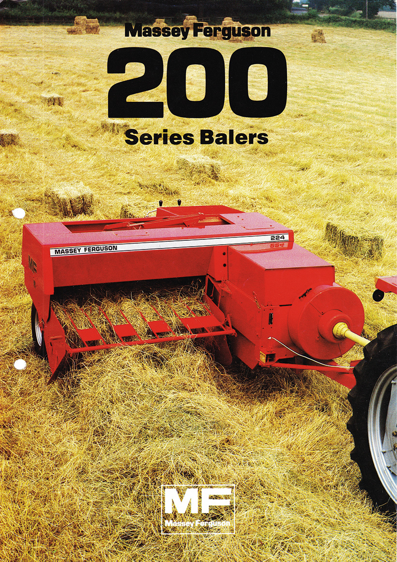
The 200 series balers were the last conventional balers built by MF at the Marquette factory.
Round bales
By the mid-1980s, most farms were making round bales or clamp silage, rather than conventional bale hay, and the demand for conventional balers was greatly reduced. Massey Ferguson was also going through turbulent financial times and, in 1984, the Marquette factory, where the European combines and balers were made, was closed. Massey Ferguson turned to the French company Rivierre-Casalis to provide conventional balers, which would be marketed as the No. 2-4 range.
Many examples of the balers produced are still to be found, and many of the older models see the light of day, at least once a year, to bale the odd meadow or attend a working day. The MF 124-228 machines are often still used for frontline work as, although they’re out-paced by more modern machines, the suretie knotter is still well regarded and hard to beat for non-stop baling. This fact is reflected in the availability and cost of such models; they rarely come up for sale and, when they do, they command good money.
ACKNOWLEDGEMENTS
My thanks to Melvin Stamp, Edward Garner, Alan Glover and Brian Davies, for answering my requests for contemporary working photographs of the balers, as discussed through the Friends of Ferguson Heritage Ltd website.
Buy a money-saving subscription to Classic Massey & Ferguson Enthusiast magazine by clicking here


