Claymills steam pumping station
Posted by Chris Graham on 2nd June 2022
David Reed visits the wonderful Claymills steam pumping station, regarded by English Heritage as the most complete in the country.
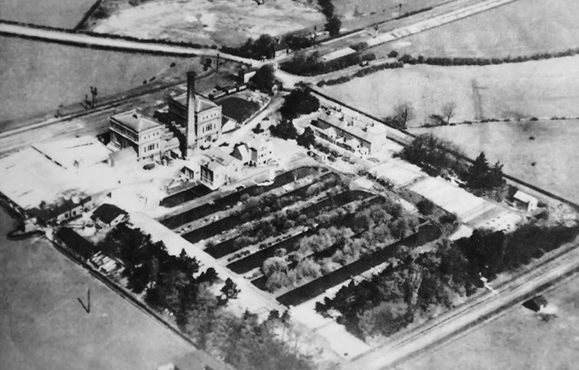
The pumping station before WWII. Now demolished, the lime sheds are on the left and the four cottages in the centre.
Travelling on the train between Derby and Burton upon Trent, the train passes an old industrial-looking building to which many people will not give a second glance. Complete with tall chimney, the building does indeed belong to the Victorian era, and served the town of Burton upon Trent from its opening in 1885 until the site closed in 1971. This is Claymills Victorian Pumping Station, which was responsible for pumping sewage from the town by utilising four immense steam engines. Now in the hands of The Claymills Victorian Pumping Engines Trust Ltd, it has been described by English Heritage as the most complete pumping station in the country, housing the four original engines, two of which can be steamed, with the other two in the process of restoration.
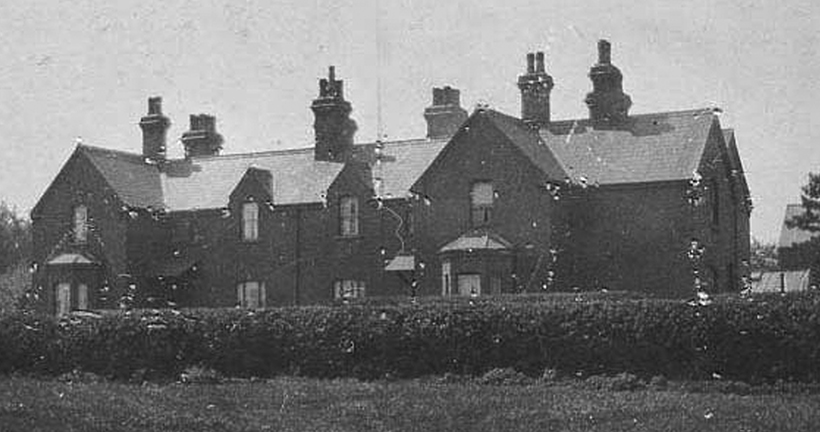
The four worker’s cottages that were built on site. They have now been demolished.
The reason for the need of such a large station is connected to the main industry in the town – brewing. The town of Burton upon Trent is located in the narrowest part of the upper Trent Valley in Staffordshire, and the Needwood plateau to the north-west of the town is rich in gypsum deposits. Rain washed these minerals down to Burton along the rock strata, with the ‘gyseous water’ containing large amounts of magnesium sulphate and calcium sulphate, both of which gave superior characteristics to the brewing water.
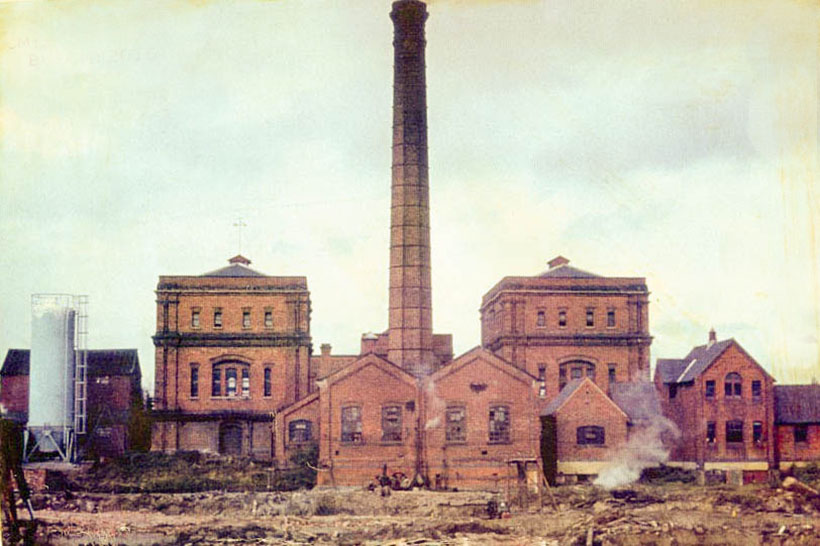
The pumping station looking a little derelict in 1968.
This led to the rapid development of the brewing industry in the town, especially when the new product of India Pale Ale was developed in the late 1820s. By 1831, the town’s output was 50,000 barrels a year, and after the opening of the Birmingham & Derby Junction Railway in 1839 it rose to 78,000 barrels by 1850 and 145,000 barrels by 1855. This rapid growth though led to problems in the town, as there was no water supply or sewage system in place. Water was drawn from wells, and effluent was discharged into the nearest stream, which became nothing more than open sewers.
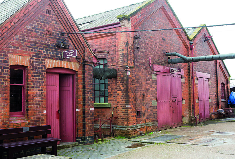
The sheds at the rear of the main building which house the dynamo shed, blacksmith’s forge and workshop as well as the Stoker’s Rest café.
This waste comprised of a lot of foul-smelling, high-temperature, sulphate-rich effluent from the breweries containing hops and yeast which decomposed rapidly. The result was a repugnant smell in the town, which was especially strong during the summer months. Something had to be done and after much discussion, in 1866 a sewer was built along with five precipitation tanks and open sludge drying areas at Claymills, although these drying areas were still a source of an obnoxious smell. Despite experiments being carried out, such as adding lime to the sewage, because the brewing industry continued to expand, a new solution needed to be found. Eventually it was decided that the sewage should be treated by intermittent downward filtration process on a sewage farm. The problem was that the chosen site was around 80 feet higher than the previous location, so a pumping station had to be built. Four large engines made by Gimson & Company of Leicester at a cost of £20,000 and were capable of pumping 125,000 gallons an hour were acquired.
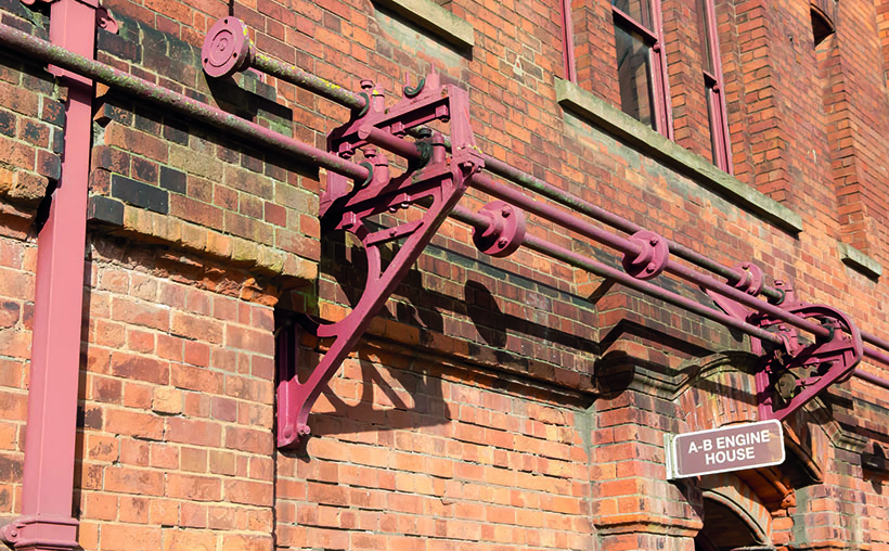
Crankshafts can be seen on the outside of Engine House No. 1, which houses engines A and B.
The complex fully started operating in 1885, and continued to pump the sewage up to the farm until 1969 when the current treatment works were commissioned, and engines A and B were retired. Engines C and D continued to work for the next two years though, being used to pump sludge to the farm until superseded by electric pumps in 1971 and the closure of the station.
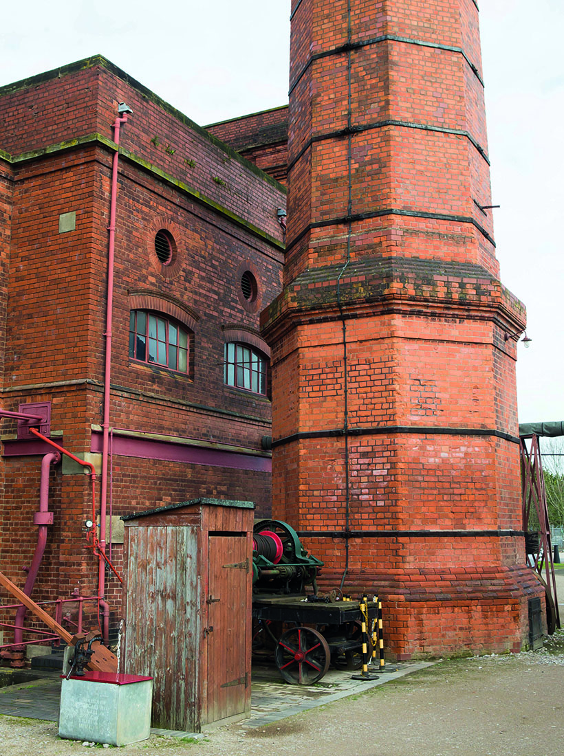
The base of the chimney stands in front of the boiler house where five Lancashire boilers provide the power for the engine.
After closure, there was a strong possibility that the entire site would be demolished but by the efforts of local people, the buildings were given Grade II status by English Heritage, which was subsequently upgraded to Grade II* status. The site was acquired by Severn Trent, through the 1974 Water Act, who put out some information in the Stationary Engine Research Group’s newsletter which was seen by Dave Wombwell. He got together a group of like-minded individuals who were interested in taking over the site with restoration in mind. The problem lay with the state of buildings themselves, with Severn Trent not allowing any of the group on site until substantial repairs were carried out. Funded by Severn Trent Water and English Heritage, it was not an easy task, work included roof repairs, the removal of asbestos and the rebuilding the top 30 feet of the chimney. But by 1993 the site was declared safe, with the keys to the site being handed over to the group who then formed The Claymills Pumping Engines Trust Ltd – restoration could begin.
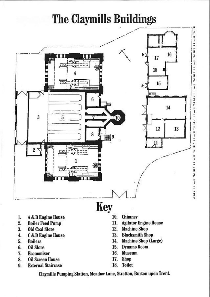
A plan of the pumping station.
The aim was to restore the engines and buildings to allow the pumping station to be opened to the public. As for the pumping station itself, the two engine houses, boiler house and chimney were constructed by Hodges of Burton between 1884 and 1886. But it is the two engine houses that were the mainstay of the pumping process. Each house still contains the original pair of Woolf compound rotative beam pumping engines, with engines A and B being situated in engine house number one, and engine C and D in number two. The four engines were basically identical, the only difference that they were arranged as a mirror image.
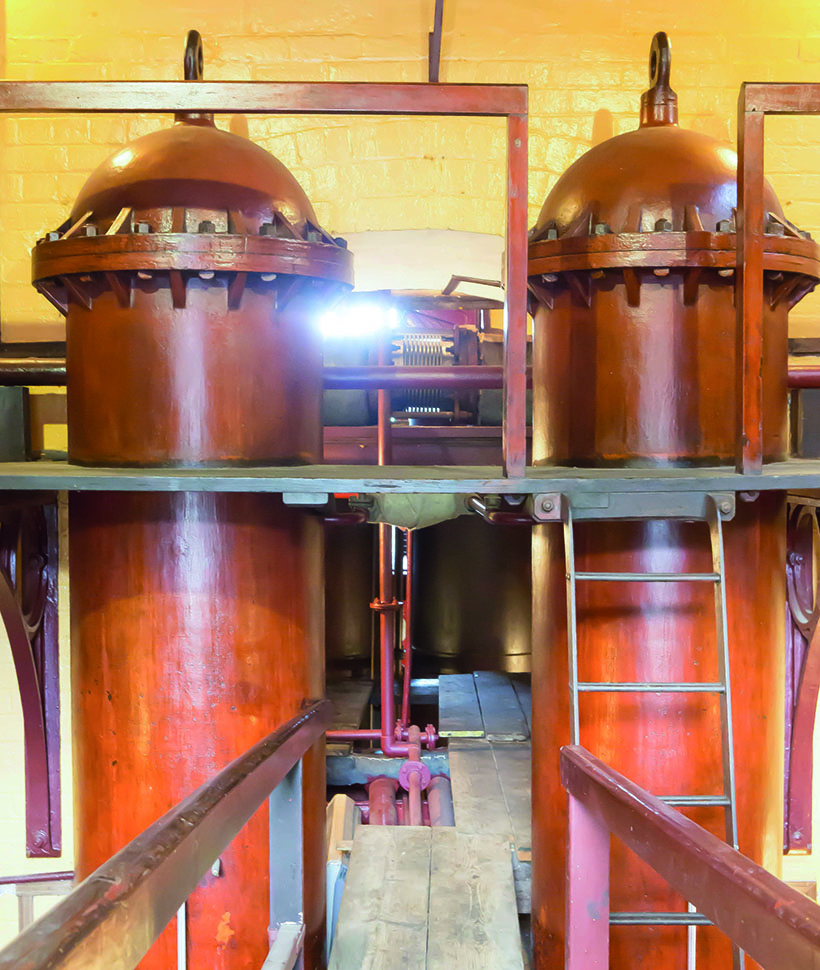
The air vessels for engines C and D in Engine room No 2. The narrow walkway behind takes you under the engine itself.
Looking at some of the technical aspects of the engines for a moment, each one is fitted with two cylinders, the high pressure one having a 24in bore with a six-foot stroke while the low-pressure cylinder has a 38in bore and eight-foot stroke. Steam is distributed by means of double beat ‘Cornish’ valves mounted in upper and lower valve chests, which are operated from the underfloor camshaft. These are worked manually when the engine is being started though, with levers being used to open and close the valves on the cylinders in a designated sequence.
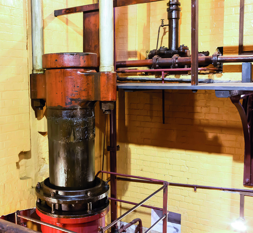
The sewage pump on engine C. It would move 90 gallons of sewage on each stroke.
It took three men to start each engine, one on the steam wheel throttle and two on the levers sequence, however once the engine was turning, the valves were opened and closed automatically via the cam shaft. In 1908, a horizontal single-cylinder barring engine, built by Roller, Mower & Engineering Co of Repton in Derbyshire, was installed in each engine room for turning the beam engines. This ensured that they were in the correct position for warming and starting, or to rotate the engine for maintenance purposes.
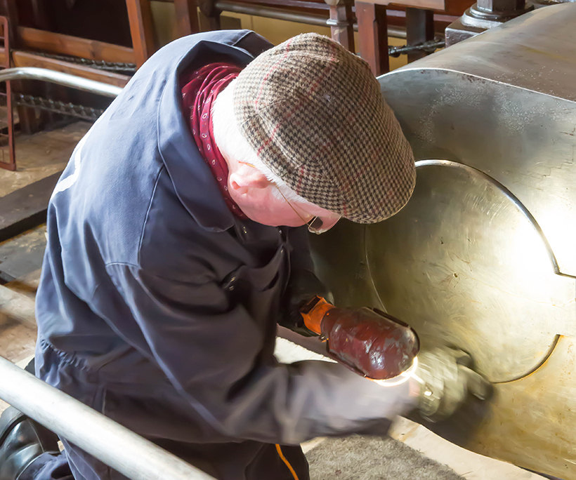
Volunteer Alastair Scales is seen cleaning the main crank on C engine. The trust relies on volunteers like Alastair to maintain the engines with their engineering skills.
When running, the steam powers the high pressure cylinder before being transferred into the low pressure one. It then passes into the condenser where a jet of cold water is sprayed into the steam which creates a vacuum to pull the piston down. The camshaft is driven from the crankshaft by three bevel gears, while the Watt-type governor is also driven from a point on this gear train. As for the beam itself, it is a somewhat rare type, being of a riveted wrought iron plate construction and is 26 feet in length. Weighing in at 13 tons, it is carried on 12in diameter plain bearings, while the cylinders act on only one end of the beam via Watt’s parallel motion.
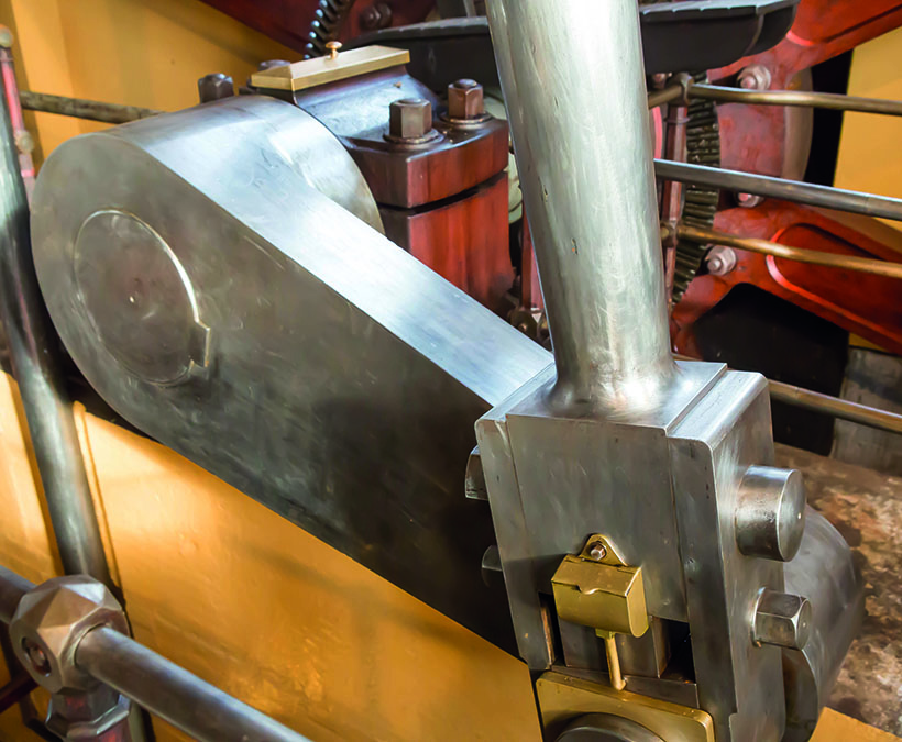
The main crank on engine D, cleaned and ready for use.
The connecting rod drives of 4ft, which is mounted on a 12in diameter crankshaft. This carries the flywheel which has an impressive diameter of 24 feet and weighs in at 24 tons. Not all the engines were in operation at the same time, instead they ran in pairs, although a third engine was occasionally employed during times of heavy load. These operated at about 10rpm with the two engines having a combined pumping rate of 5.5 million gallons per day. Each engine house also contained a single-cylinder horizontal air compressing engine, which was used to regulate any shock waves of discharged sewage.
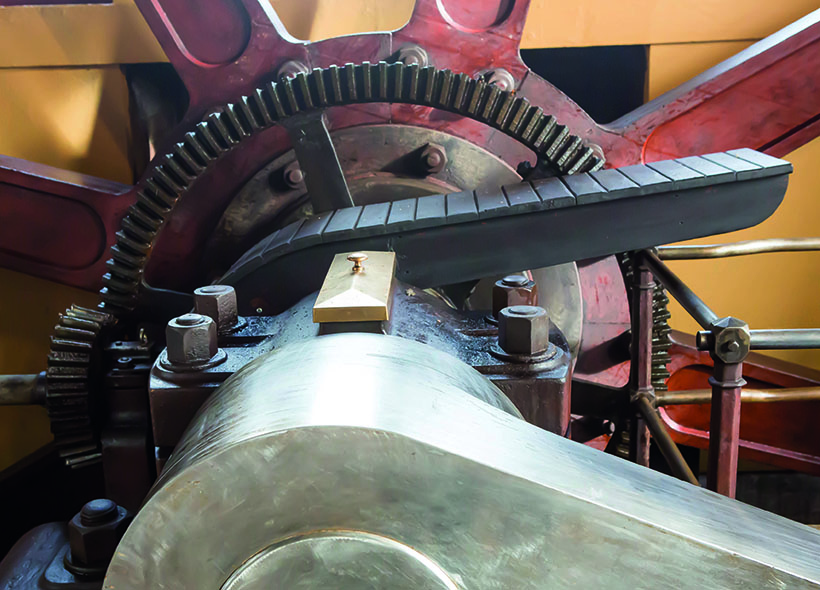
Main crank on engine D with the 90 degree bevelled gears that turn the crankshafts, all in top condition.
Also requiring the driver’s attention was a large depth gauge on the engine house wall. This would indicate the depth of sewage outside, as soon as it got to eight feet in depth the driver would speed up the engine to get rid of the sewage quickly.
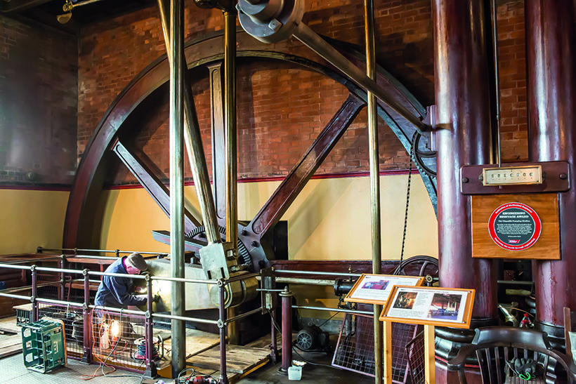
Alastair Scales is seen cleaning engine C. The flywheel behind shows its true size, having a 24-foot diameter and weighing 24 tons.
During the station’s working days, it wasn’t all plain sailing with the engines, which is illustrated by an incident that took place on 6 July 1922, that resulted in all four beam engines being modified. It was 2.45pm when engine D was being started to assist with a high peak load. In order to allow the three engines to run together, the other two engines were slowed down, while engine D was being started, and then all three engines were to run up to full speed. Unfortunately though, things went wrong when the steam valve on engine D jammed fully open and the engine ran away, breaking the brackets on the pump linkage motion and bending the wrought iron fish-belly pump rods. As a result of this incident, the pump rods on all four engines were replaced with stainless steel ones. Also modified were the main steam valves which were reversed, resulting in less wear as well as allowing the steam pressure itself to help close them.
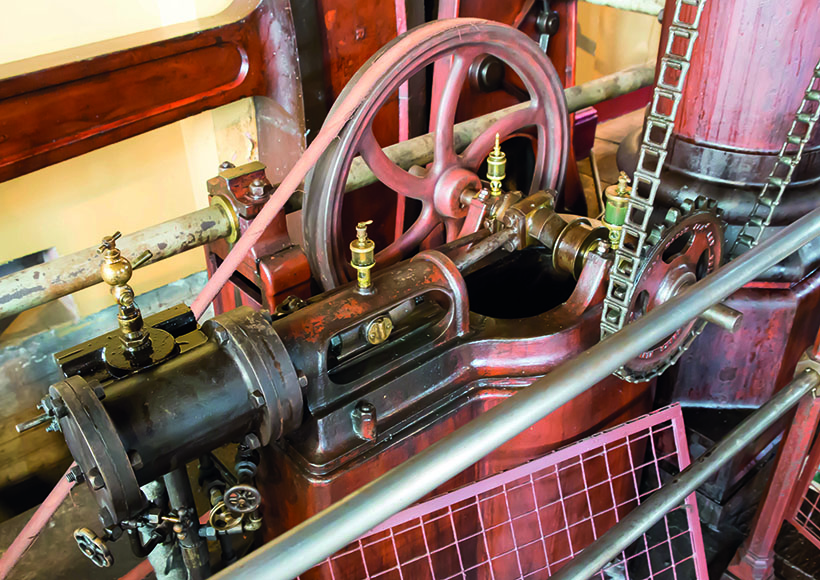
The barring engines were built by Roller, Mower & Engineering Co of Repton in Derbyshire. This example was used to ensures that Engine B and C were in the correct position for warming and starting.
To assist with any heavy lifting, and located above the beams, and at the top of the building, is a manually operated bridge crane that consists of a pair of wrought fish-bellied girders within cast iron frames. It runs on Brunel type rails that are set into the building’s side walls which allows the crane to traverse the length of the building. The driving gear is located in the ‘crab’ which can move across the whole width of the crane as required, and is fitted with a wire rope and wrought iron hook and chain.
This features comes from a recent issue of Old Glory, ands you can get a brilliant, money-saving subscription to the magazine simply by clicking HERE