The amazing Bregazzi steam buggy!
Posted by Chris Graham on 15th January 2022
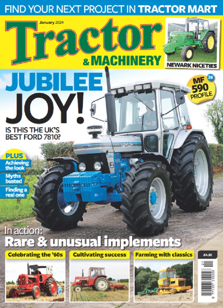
Part 1: Jonathan Bregazzi tells the story of the amazing Bregazzi Steam Buggy, which he designed and built himself at home.
Jonathan’s amazing, home-designed and built Bregazzi Steam Buggy! Here the unfinished vehicle is out on test.
I’ve loved steam since I was a youngster. Some of my earliest memories are of watching the steam train on the Isle of Man railway as it travelled on the, now closed, Peel line. As a teenager I was thrilled to be invited to visit the engine room of the Isle of Man Steam Packet ferry, Ben-My Chree (V). I loved the atmosphere in the engine room and the thrill of operating the port turbine (under very close supervision, of course!) and that experience influenced me in my career choice when I joined the Merchant Navy, as an engineer.
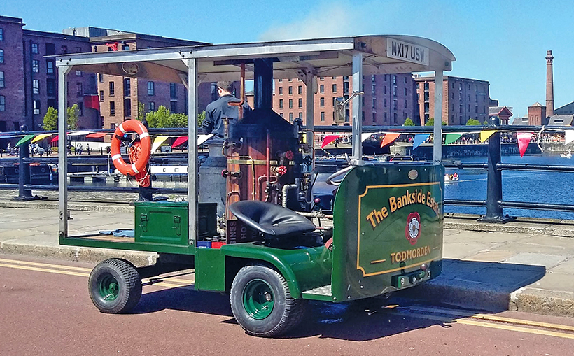
The initial alignment trial of the Buggy’s power plant. A design known as the Stuart Turner Swan, it is two Model 5a engines on a common crank.
The Buggy started as an idea I had after I’d bought some secondhand castings for a 3in Foden. Unfortunately, I was never inspired to start work on them, but it was suggested that perhaps I should build something more esoteric.
Governing factors were the space available to build it, and the transport available to move it around, so a footprint of approximately 8’x5’ was decided upon as trailers of those dimensions were readily available. Another design criteria was operator and passenger seating at the front, and so the buggy started to evolve into the front-wheel-drive, rear-wheel-steer machine that is seen today.
The two Stuart Turner 5a-type engines set up as the Stuart Turner Swan, and linked by the heavy-duty drive chain to the gearbox.
My father-in-law had built a Stuart Turner 5a a few years previously that was resting in his workshop, and that became the basis of the power plant.
Suitable running gear was researched and the subframes, gearbox and running gear designs of the average-sized lawn tractor were found to fit the bill. The chassis is constructed using 4in x ⅜in steel plate to attach the steering and gearbox subframes together. Forward of the gearbox subframe is the footwell and frame for the vehicle front, which uses a thinner section, 4in plate and 1½in angle to which the front panel and dashboard (made from the footboard of an old bed!) is attached. Rear-wheel steering is used and utilises a saddle travel wheel from an old lathe and a Teleflex cable system from a power boat.
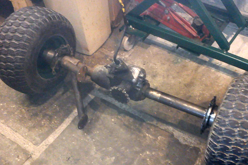
The front axle showing the gearbox with integral differential and the disc brake arrangement ready for installation.
The purchase of a secondhand, coal-fired vertical boiler, through the website of the Steam Boat Association, meant that progress could be made toward a test run.
The test revealed two important shortcomings. The wheel track was too narrow and the 5a, though giving a good turn of speed, was underpowered. So I returned to the drawing board, and came up with the plans to widen the track by a suitable amount, and to enlarge the 5a by buying another 5a and combining the two. Stuart Turner sold a bed plate and crankshaft that were designed to do this, the model being known as the Stuart Turner Swan.
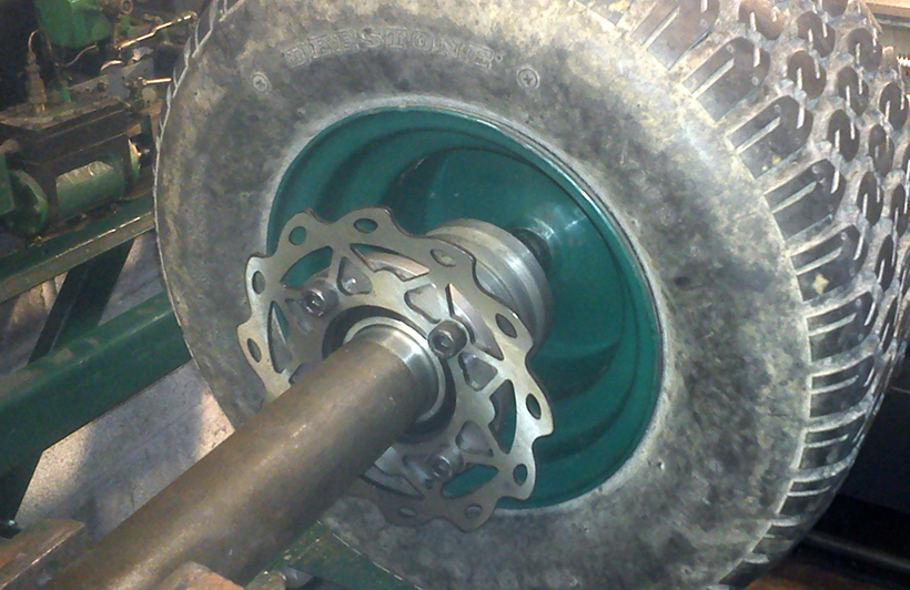
The disc brake arrangement is bolted to the rear of the main driving wheel, and is supported by a housing that runs on a bearing fitted to the outside of the axle.
This plan was developed and the buggy is currently powered by a twin-cylinder Simplex engine of that design. The crankshaft runs in three bronze plain bearings, but is supported by roller bearing plummer blocks at either end.
Steam is admitted to the valve chests via an in-line ball valve and exhausts through the smokebox, through a pipe exhausting up the chimney that is choked to ⅜in to give a suitable draft to the fire. There’s a drain fitted on the exhaust to get rid of condensate.
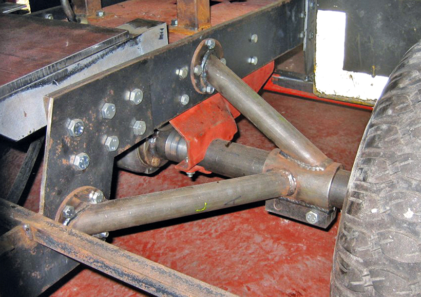
The front axle is supported on either side by horizontal and vertical struts that are attached to the main chassis…
… the gearbox is located in its own subframe which is, in turn, bolted to the chassis. The axle tubes are bolted to the gearbox through the gearbox subframe, and supported by the horizontal and vertical struts also bolted to the chassis.
The lubricator is an early Manzel design, and is driven straight from the crank. A further sprocket has been added at the front of the engine, for a water pump drive.
There’s a 1:1 chain drive to the three-speed gearbox from the rear of the engine, which then drives through a differential within the gearbox to the front wheels. This gives a road speed of about 7mph when running in third gear, with the engine doing about 600rpm.
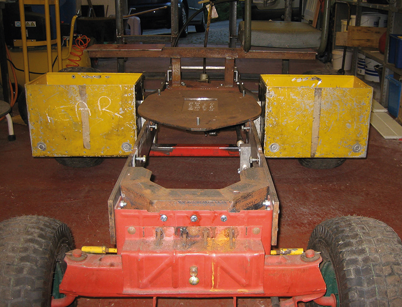
Looking forward from the rear, this view shows the chassis and steering subframe. The coal bunker is on the left and the stores box for oil and polish etc, is on the right.
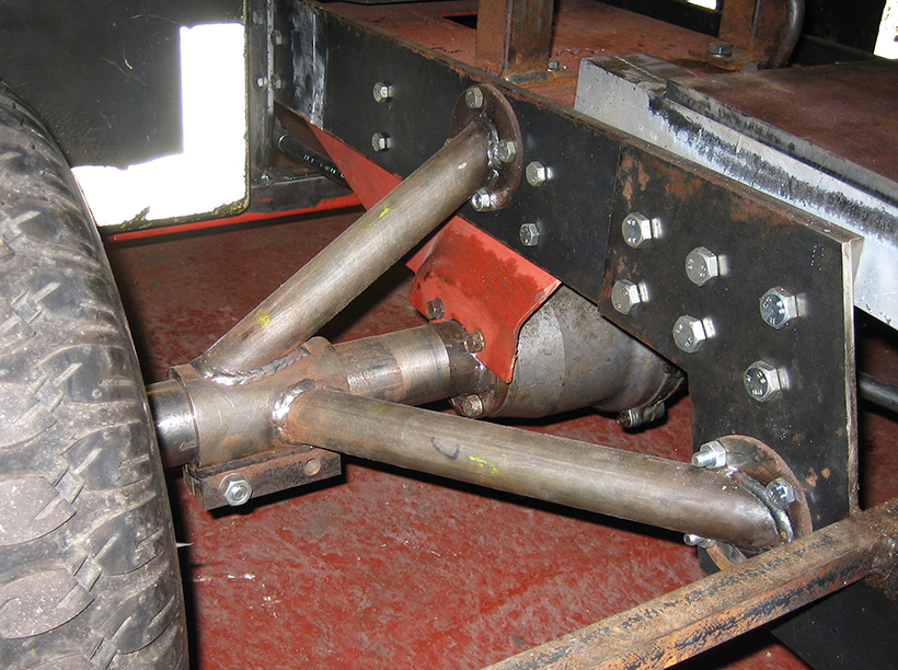
The original wheel bearings were needle roller bearings set in the gearbox castings. When the track was widened, the extra stability for the wider track was obtained by designing thick-walled tubes in which new, roller bearings run. These tubes are supported by struts that are bolted to the chassis in vertical and horizontal axes.
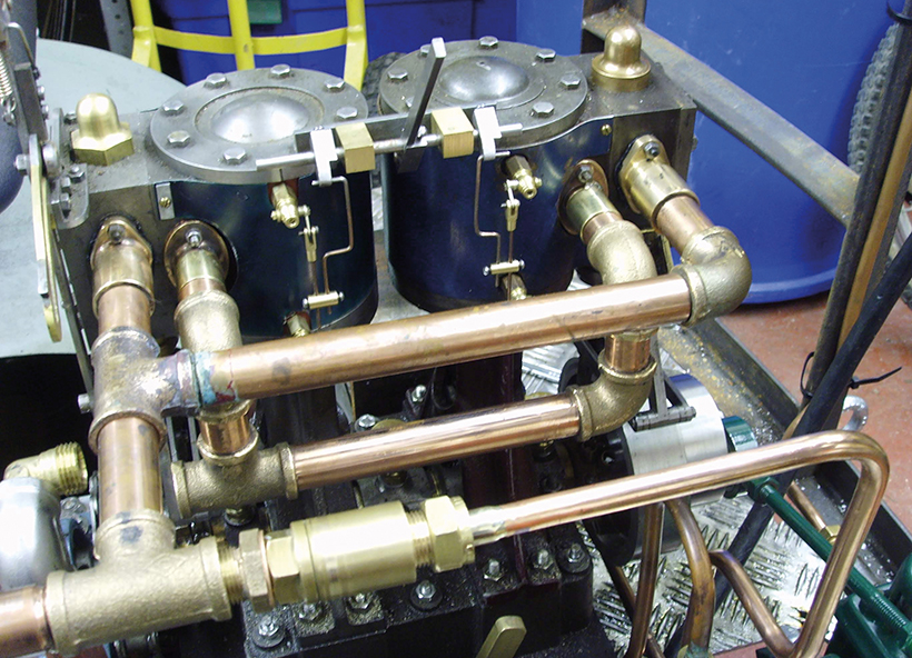
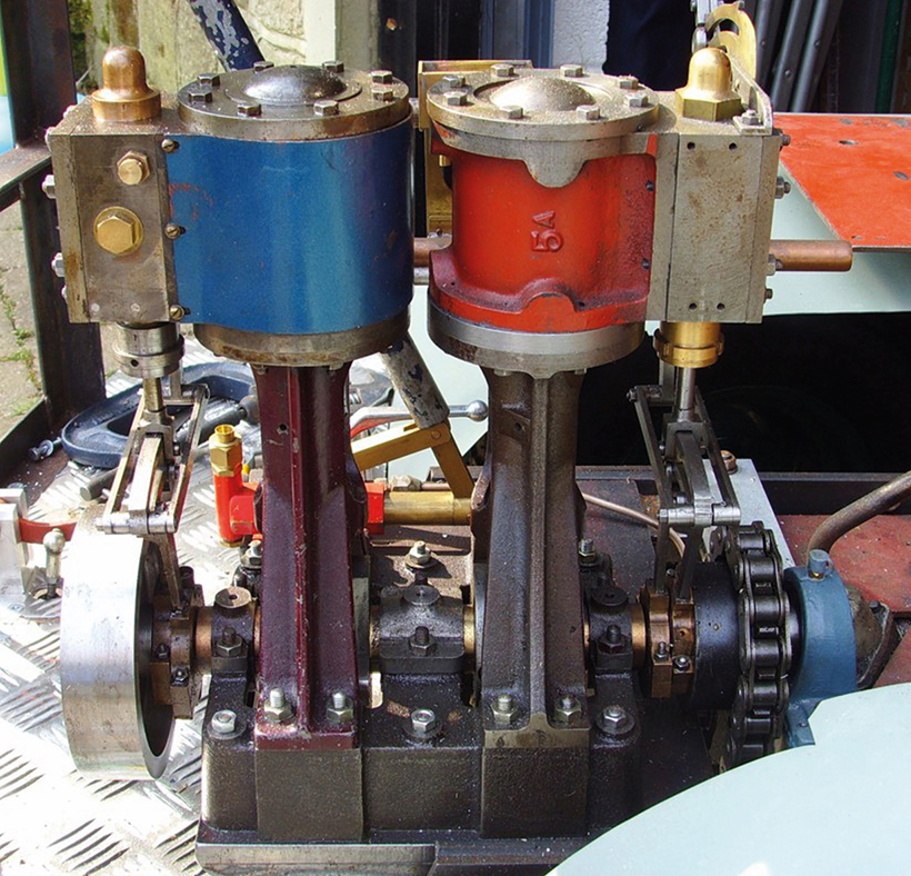
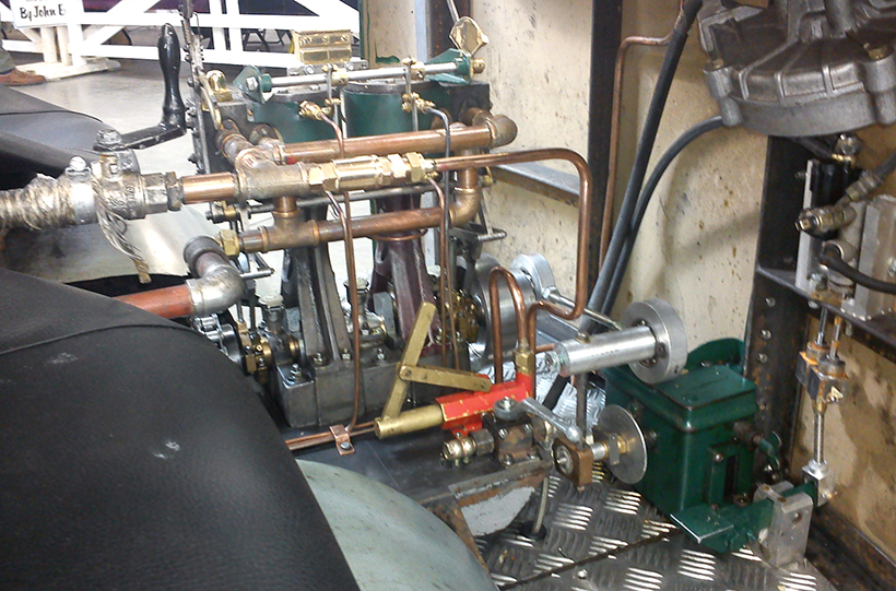
Piping in copper with bronze fittings for the steam supply, steam oil supply and exhaust for the Stuart Turner Swan power plant. The drain cock pipes are yet to be fitted.
The lawn tractor design of brakes was inadequate. Initially, hydraulic disc brakes, as used in Chinese pit bikes, were used, but these still lacked the stopping power necessary, and the system has been upgraded to one used on an MGB car, with discs bolted to the inside of the front wheels and running on a bearing that fits over the extended axle tubes.
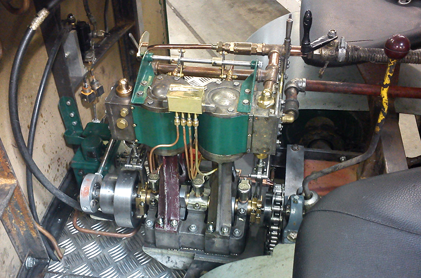
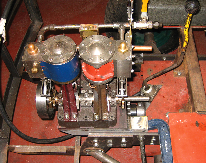
The engine all plumbed in and showing wick oilers to the trunk crosshead guides and to the main bearings.
There is an eight-pint-per-minute injector used for water supply, and that’s backed up by a hand pump. Work continues on finding and fitting a suitable engine-powered pump to supplement the injector.
The water reservoir was originally three fire extinguishers placed horizontally under the frame, but these proved to be under capacity and so were replaced with, first one and then two milk churns. These give the buggy a sense of purpose while performing a useful function.
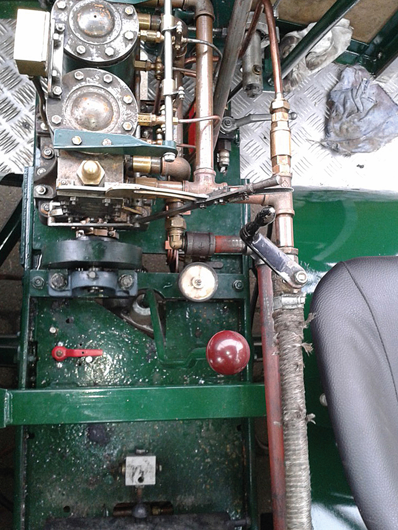
A vertical view of the engine which shows that it’s slightly off-set to allow space for the hand-operated water pump.
The front panel and the mudguards were made by a talented neighbour who’s main hobby is classic cars. The seats are designed for a mini digger and are readily available online. Behind them sit the coal bunker on one side and a space for the various comestibles used on the other. These were made from an ex-MOD aluminium box cut in half, and are supported by framework underneath. Another ex-MOD box is used as the toolbox.
Cylinder drains and the hand-operated water pump are plain to see in this view of the right-hand side of the engine.
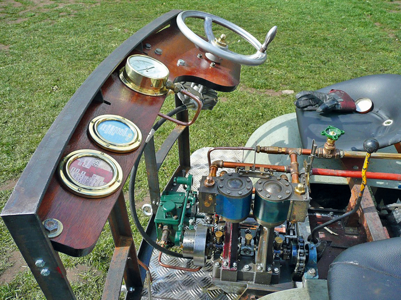
The dashboard supports the Teleflex steering gearbox originally designed for a power boat.
The boiler is a coal-fired, vertical boiler made by Alan McEwen in 1982, to his K1 design.
For a money-saving subscription to Old Glory magazine, simply click here